Circular diffuser face with circular plenum box and horizontal spigot
Circular diffuser face with circular plenum box and horizontal spigot
Square diffuser face with square plenum box and horizontal spigot

Circular diffuser face with circular plenum box and vertical spigot
Horizontal swirling air discharge
Circular and square swirl diffusers with high induction for high air change rates
■ Nominal sizes 300, 400, 500, 600, 625
■ Volume flow range 9 – 235 l/s or 31 – 846 m³/h
■ Diffuser face made of galvanised sheet steel, powder-coated
■ For supply and extract air
■ For constant and variable volume flows
■ For all ceiling systems, and with an extended border also suitable for freely suspended installation
■ Small swirl diffusers for 600 and 625 ceiling grids
■ High induction results in a rapid reduction of the temperature difference and air velocity
■ Ideal for comfort zones
Optional equipment and accessories
■ Exposed diffuser face available in RAL CLASSIC colours
■ Square plenum box with cord-operated damper blade and pressure tap
Nominal sizes
Accessories
Lip seal
Note: For circular plenum box with horizontal spigot: Lip seal only available in combination with damper blade
Square plenum box
Materials and surfaces
Diffuser face
Lip seal
Maintenance
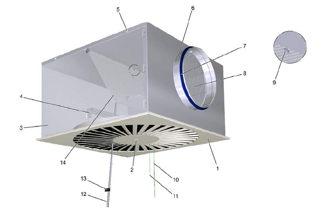
1 Diffuser face 2 Central fixing screw with decorative cap 3 Plenum box 4 Cross bar 5 Suspension hole 6 Spigot | Optional 7 Lip seal 8 Damper blade for volume flow balancing 9 Pressure tap 10 Green cord, closing the damper blade 11 White cord, opening the damper blade 12 Measuring tube 13 Text label indicating plenum box variant 14 Perforated plate as an equalising element (only for supply air) |
Nominal sizes | 300, 400, 500, 600, 625 mm |
Dimensions ceiling panel | 598 x 598 or 623 x 623 |
Minimum volume flow rate, with Δtz = -6 K | 9 – 28 l/s or 31 – 102 m³/h |
maximum volume flow, at LWA ≅ 50 dB(A) | 70 – 235 l/s or 252 – 846 m³/h |
Supply air to room air temperature difference | -12 – +10 K |
Specification text
Ready-to-install component, consisting of:
Plenum box
Diffuser face
Special characteristics
Materials and surfaces
Damper blade
Circular plenum box
Square plenum box
Lip seal
Technical data
Standards and guidelines
| FD | – | Q | – | Z | – | H | – | M | – | L | / | 500 x 598 | / | P1 - RAL 9016 |
| | | | | | | | | | | | | | | | | |||||||
| 1 | 2 | 3 | 4 | 5 | 6 | 7 | 9 |
1 Type
FD Swirl diffuser
2 Construction style
R circular
Q square
3 System
Z Supply air
A Extract air
4 Spigot
H with horizontal spigot
V with vertical spigot (the plenum box is always circular)
5 Damper blade for volume flow balancing
No entry: without damper blade
M with damper blade
MN with cords and pressure tap (only with square plenum box)
6 Accessories
No entry: without accessories
L with lip seal
7 Nominal size [mm]
Nominal size swirl diffuser x ceiling tile size
Nominal size swirl diffuser
300, 400, 500, 600, 625
Ceiling tile size (only with construction style Q)
No entry: Ceiling tile size according to nominal size swirl diffuser
598 square ceiling tile, 598 x 598 mm (not for nominal size 625 swirl diffuser)
623 square ceiling tile, 623 x 623 mm
8 Exposed surface
No entry: powder-coated, RAL 9010 (pure white)
P1 powder-coated; specify RAL CLASSIC colour
Gloss level
RAL 9010 GU 50
RAL 9006 GU 30
All other RAL colours GU 70
Note: Circular plenum boxes with a horizontal spigot have either no damper blade and no lip seal or both a damper blade and a lip seal. Features 2 and 4 define the plenum box geometry.
Order example: FD-Q-Z-H-M-L/500×598/P1-RAL9016
| Type | FD – Swirl diffuser |
| Construction style | square |
| System | Supply air |
| Spigot | with horizontal spigot |
| Damper blade for volume flow balancing | with damper blade |
| Accessories | with lip seal |
| Nominal size [mm] | Nominal size 500, square ceiling panel, 598 x 598 mm |
| Exposed surface | powder-coated, RAL 9016 (traffic white), GU 70 |
Share page
Rekommendera denna sida
Rekommendera denna sida ved att senda en link på mail.
Dela sidan
Tack för din rekommendation!
Din rekommendation har skickats och bör anlända inom kort tid.
Kontakt
Vi är här for dig

Vänligen skriv ditt meddelande och ärende
Kontakt
Tack for ditt meddelande!
Ditt meddelande har skickats och kommer att behandlas inom kort tid. Vår serviceavdelning återkommer til dig så snart vi har möjlighet.
Kontakt
Vi är här for dig
Vänligen skriv ditt meddelande och ärende
Kontakt
Tack for ditt meddelande!
Ditt meddelande har skickats och kommer att behandlas inom kort tid. Vår serviceavdelning återkommer til dig så snart vi har möjlighet.


