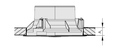
Square face style with square plenum box
Circular face style with circular plenum box

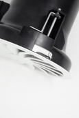
Circular swirl diffuser with spigot for connection to a vertical duct
Gently sloped, flat border (shown in a continuous ceiling)
Three-dimensional blade contour
Circular and square ceiling swirl diffusers with fixed air control blades, for high volume flow rates at low sound power levels and low differential pressure due to innovative polymer technology
Optional equipment and accessories
Application
Special features
Diffuser face with gently sloped, flat border – only 3 mm high
Nominal sizes
Variants
Connection
Construction features
Square plenum boxes with horizontal spigot for nominal sizes 300, 300L, 600H and 625
Circular plenum boxes with horizontal spigot for nominal sizes 250, 400L, 400H and 600
Plenum box for supply air, with an optimised equalising element that ensures a uniform airflow through the diffuser face
Simple installation of the diffuser face due to central fixing screw with cap
Spigot for nominal sizes 160 and 250 and vertical connection to the ductwork
Materials and surfaces
Diffuser face, spigot and damper blade made of ABS plastic, UL 94, V-0, flame retardant
Plenum box and cross bar made of galvanised sheet steel
Diffuser face coated RAL 9010, pure white
Standards and guidelines
Maintenance

Ceiling swirl diffusers in air conditioning systems create a swirl to supply air to rooms. The resulting airflow induces high levels of room air, thereby rapidly reducing the airflow velocity and the temperature difference between supply air and room air. Ceiling swirl diffusers allow for large volume flow rates. The result is a mixed flow ventilation in comfort zones, with good overall room ventilation, creating only very little turbulence in the occupied zone.
Type AIRNAMIC ceiling swirl diffusers have fixed blades with three-dimensionally profiled contours. This allows for high volume flow rates and low sound power levels. The supply air to room air temperature difference can range from -10 to +10 K.
A damper blade simplifies volume flow rate balancing for commissioning.
To give rooms an aesthetic, uniform look, Type AIRNAMIC diffusers may also be used for extract air. There is then no equalising element.
| Nominal sizes | 160, 250, 300, 400, 600, 625 mm |
Minimum volume flow rate, with Δtz = -6 K | 5 – 76 l/s or 16 – 274 m³/h |
| Maximum volume flow rate, with LWA ≅ 50 dB(A) | 44 – 385 l/s or 159 – 1386 m³/h |
| Supply air to room air temperature difference | -12 – 10 K |
The quick sizing tables give a good overview of the volume flow rates and the corresponding sound power levels and differential pressures. The minimum volume flow rates apply to a supply air to room air temperature difference of -6 K. The maximum volume flow rates apply to a sound power level of approx. 50 dB (A) with damper blade position 0°. Exact values for all parameters can be determined with our Easy Product Finder design program.
AIRNAMIC-Q-Z-H (supply air) soundpower level and total differential pressure
| NS | qv [l/s] | qv [m³/h] | 0° | 45° | 90° | |||
|---|---|---|---|---|---|---|---|---|
| Δpₜ [Pa] | LWA [dB(A)] | Δpₜ [Pa] | LWA [dB(A)] | Δpₜ [Pa] | LWA [dB(A)] | |||
| 300L | 13 | 47 | 1 | <15 | 2 | <15 | 2 | <15 |
| 300L | 40 | 144 | 9 | 24 | 16 | 24 | 23 | 24 |
| 300L | 68 | 245 | 27 | 37 | 45 | 38 | 65 | 39 |
| 300L | 95 | 342 | 539 | 50 | 89 | 51 | 127 | 51 |
| 300H | 16 | 58 | 1 | <15 | 2 | <15 | 4 | <15 |
| 300H | 55 | 198 | 15 | 22 | 27 | 24 | 41 | 27 |
| 300H | 130 | 468 | 86 | 50 | 150 | 51 | 232 | 54 |
| 600, 625 | 76 | 274 | 3 | <15 | 7 | <15 | 13 | 18 |
| 600, 625 | 180 | 648 | 18 | 24 | 41 | 31 | 72 | 41 |
| 600, 625 | 285 | 1026 | 44 | 40 | 102 | 47 | 180 | 58 |
| 600, 625 | 385 | 1386 | 80 | 50 | 185 | 59 | 329 | 71 |
| 300H | 90 | 324 | 41 | 37 | 72 | 39 | 111 | 42 |
0°, 45°, 90°: Damper blade position
AIRNAMIC-R-Z-H (supply air), sound power level and total differential pressure
| NS | qv [l/s] | qv [m³/h] | 0° | 45° | 90° | |||
|---|---|---|---|---|---|---|---|---|
| Δpt [Pa] | LWA [dB(A)] | Δpt [Pa] | LWA [dB(A)] | Δpt [Pa] | LWA [dB(A)] | |||
| 250 | 12 | 42 | 2 | <15 | 2 | <15 | 2 | <15 |
| 250 | 42 | 152 | 20 | 29 | 25 | 29 | 32 | 29 |
| 250 | 73 | 262 | 59 | 42 | 75 | 42 | 95 | 42 |
| 250 | 103 | 373 | 119 | 50 | 151 | 50 | 191 | 50 |
| 400L | 17 | 61 | 1 | <15 | 1 | <15 | 2 | <15 |
| 400L | 55 | 198 | 9 | 25 | 14 | 25 | 20 | 29 |
| 400L | 95 | 342 | 27 | 38 | 41 | 39 | 59 | 41 |
| 400L | 135 | 486 | 55 | 50 | 82 | 51 | 118 | 52 |
| 400H | 24 | 86 | 1 | <15 | 2 | <15 | 4 | <15 |
| 400H | 75 | 270 | 14 | 26 | 21 | 28 | 34 | 28 |
| 400H | 130 | 468 | 41 | 40 | 64 | 40 | 101 | 44 |
| 400H | 180 | 648 | 79 | 50 | 123 | 50 | 193 | 54 |
| 600, 625 | 57 | 205 | 2 | <15 | 4 | <15 | 8 | <15 |
| 600, 625 | 160 | 576 | 17 | 27 | 35 | 28 | 60 | 36 |
| 600, 625 | 265 | 954 | 47 | 40 | 97 | 45 | 163 | 54 |
| 600, 625 | 365 | 1314 | 89 | 50 | 185 | 58 | 310 | 66 |
0°, 45°, 90°: Damper blade position
AIRNAMIC-R-Z-V (supply air), sound power level and total differential pressure
NS | qv [l/s] | qv [m³/h] | Δpₜ [Pa] | LWA [dB(A)] |
|---|---|---|---|---|
160 | 5 | 16 | 1 | <15 |
160 | 18 | 64 | 13 | 26 |
160 | 31 | 111 | 39 | 40 |
160 | 44 | 159 | 80 | 50 |
250 | 12 | 42 | 1 | <15 |
250 | 44 | 159 | 11 | 24 |
250 | 77 | 277 | 33 | 40 |
250 | 109 | 394 | 68 | 50 |
Specification text
Ceiling swirl diffusers with square or circular diffuser face, for comfort zones with particularly demanding requirements of aesthetics and design. Supply air and extract air variants. Excellent aerodynamic and acoustic function due to air control blades with optimised aerofoil contours, for horizontal swirling air discharge, creating high levels of induction. For installation into all types of suspended ceilings. Ready-to-install component that consists of a diffuser face with either a plenum box or a spigot. Plenum box with horizontal spigot, cross bar and either drilled holes or suspension lugs, with a damper blade for volume flow rate balancing and a lip seal on the spigot, supply air spigot with equalising element. Alternatively, spigot for nominal sizes 160 and 250 for the direct connection to ductwork, diffuser face fixing without any tools. The diffuser face can be fixed to the cross bar with a central screw, concealed with a cap. Spigots are suitable for ducting according to EN 1506 or EN 13180. Sound power level of the air-regenerated noise measured according to EN ISO 5135.
Special features
Diffuser face with gently sloped, flat border – only 3 mm high
Materials and surfaces
Diffuser face, spigot and damper blade made of ABS plastic, UL 94, V-0, flame retardant
Plenum box and cross bar made of galvanised sheet steel
Diffuser face coated RAL 9010, pure white
Technical data
| AIRNAMIC | – | R | – | Z | – | H | / | 400H | / | S1 – RAL… |
| | | | | | | | | | | | | |||||
| 1 | 2 | 3 | 4 | 5 | 6 |
| Style | Circular |
| Air conditioning system | Supply air |
| Connection | horizontal |
| Nominal size | 400H |
| Surface | RAL 9010, pure white |
AIRNAMIC-Q/600
Variant
Nominal sizes
300L, 300H, 600, 625Parts and characteristics
Construction features
Variant
Nominal sizes
Parts and characteristics
Plenum box for horizontal duct connection
Spigot for connection to a vertical duct
Construction features


NS | □Q₁ | H₁ | □Q₃ | H₃ | ∅D | A | C | ① | m [kg] |
|---|---|---|---|---|---|---|---|---|---|
| 300L | 298 | 3 | 290 | 250 | 158 | 139 | 60 | AK-H-Q/300 | 3 |
| 300H | 298 | 3 | 290 | 250 | 158 | 139 | 60 | AK-H-Q/300 | 3 |
| 600 | 598 | 3 | 567 | 345 | 248 | 194 | 60 | AK-H-Q/600 | 8.7 |
| 625 | 623 | 3 | 567 | 345 | 248 | 194 | 60 | AK-H-Q/600 | 8.7 |
NS | ØD1 | H1 | ØD3 | H3 | ØD | A | C | ① | m [kg] |
|---|---|---|---|---|---|---|---|---|---|
250 | 250 | 3 | 274 | 293 | 158 | 189 | 60 | AKR1* | 2.4 |
400L | 400 | 3 | 362 | 290 | 198 | 166 | 60 | AKR2 | 4 |
400H | 400 | 3 | 362 | 290 | 198 | 166 | 60 | AKR2 | 4 |
600 | 600 | 3 | 573 | 344 | 248 | 195 | 60 | AKR5 | 7.5 |
① Plenum box
* AIRNAMIC 250 is fitted with a transition piece.
Weights apply to the supply air variant.
AIRNAMIC-R-*-V
NS | ØD1 | H1 | ØD3 | H3 | ØD4 | A1 | ØD | C |
|---|---|---|---|---|---|---|---|---|
160 | 160 | 3 | 144 | 117 | 146 | 0.5 – 30 | 98 | 50 |
250 | 250 | 3 | 222 | 117 | 225 | 0.5 – 30 | 158 | 50 |
NS | □Q2 | □Q1 | Aeff [m2] |
|---|---|---|---|
300L | 262 | 298 | 0.0139 |
300H | 262 | 298 | 0.0175 |
| 600 | 539 | 598 | 0.0616 |
625 | 539 | 623 | 0.0616 |
NS | ∅D₁ | ∅D₂ | Aeff [m2] |
|---|---|---|---|
| 160 | 160 | 132 | 0.0036 |
| 250 | 250 | 210 | 0.0098 |
| 400L | 400 | 352 | 0.0186 |
| 400H | 400 | 352 | 0.0258 |
| 600 | 600 | 546 | 0.0504 |


Innovation
Type AIRNAMIC swirl diffusers meet the most demanding requirements of technical function, comfort, and design. The unique design of the air control blades, a specially developed equalising element, and the innovative plenum box result in high volume flow rates, a low sound power level and low differential pressure. The air control blades have three-dimensionally profiled contours to create an efficient swirl. As a consequence, the airflow velocities and temperature differences in the occupied zone are very low, and the level of comfort is excellent. The production of these unusually contoured blades is only possible by the use of high-quality plastics and by applying innovative production technology.
The exceptionally aesthetic air control blades allow for perfect architectural integration of the circular or square swirl diffuser and therefore make for an important design element for building owners and architects. A spigot with double lip seal provides a low-leakage connection of the plenum box to the ducting, and a lockable damper blade for volume flow rate balancing simplifies commissioning.
Installation and commissioning
Note: These are schematic diagrams to illustrate the installation details.
Volume flow rate balancing
When several diffusers are connected to just one volume flow controller, it may be necessary to balance the volume flow rates.
Share page
Rekommendera denna sida
Rekommendera denna sida ved att senda en link på mail.
Dela sidan
Tack för din rekommendation!
Din rekommendation har skickats och bör anlända inom kort tid.
Kontakt
Vi är här for dig

Vänligen skriv ditt meddelande och ärende
Kontakt
Tack for ditt meddelande!
Ditt meddelande har skickats och kommer att behandlas inom kort tid. Vår serviceavdelning återkommer til dig så snart vi har möjlighet.
Kontakt
Vi är här for dig
Vänligen skriv ditt meddelande och ärende
Kontakt
Tack for ditt meddelande!
Ditt meddelande har skickats och kommer att behandlas inom kort tid. Vår serviceavdelning återkommer til dig så snart vi har möjlighet.


